Wide-Band MEMS Microphones Application Guide
Wide-Band MEMS Microphones Application Guide
Microphone Placement within a Product
When designing a PUI Audio MEMS microphone into your product, careful PCB placement and sound hole position need to be considered to minimize noise. The microphone should be placed to avoid antennae, amplifiers, motors, power supplies, or any other devices that may create noise interference.
Additionally, microphones should not be placed on the same PCB as spring contact or surface mount speakers, as the vibration from the speaker is often transmitted to the microphone through the PCB, creating noise, echo, or feedback.
Microphone External Sound Hole Placement on a Product’s Housing
The external sound hole on a product should be limited in distance from, and larger in diameter than, the sound hole on the microphone.
A direct path from the microphone’s sound hole (also referred to as the Acoustic Port) to the exterior of a product’s housing is required for optimum frequency response and to minimize unwanted noise from entering the microphone.
Placing the external sound hole on a flat surface simplifies the design of a gasket between the housing and the microphone sound hole.
Microphone Sound Channel Design
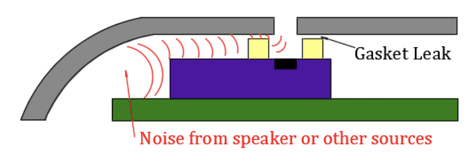
When designing the sound channel that connects the external sound hole to the microphone’s sound hole, first ensure that there is no leak by gasketing the area between the external sound hole and the microphone sound hole.
 |
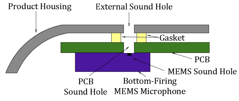 |
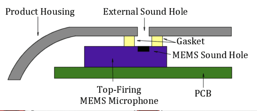
Many echo and feedback problems are caused by a leaky gasket between the sound hole between a top-firing microphone and the housing or between the bottom-firing microphone’s PCB and the housing. Please ensure the gasket is fully compressed to eliminate potential problems and/or a degradation in performance.
The sound channel should be kept as short as possible and larger in diameter than the microphone sound hole for top-firing microphones or be greater than or equal to the diameter of the PCB sound hole for bottom-firing microphones.
The diameter of gasket should be as close to the same size as the external sound hole to prevent creating a Helmholtz resonating chamber.
A long, thin or short, wide sound channel can “tune” the microphone, creating a peak in response between 10 kHz to 15 kHz, followed by a steep roll-off in frequency response thereafter.
Top-Firing Microphones: The diameter of the external sound hole and channel created by the gasket should be at least 0.1mm larger in diameter than the microphone’s sound hole.
Bottom-Firing Microphones: The diameter of the sound hole on the PCB should be at least 0.5mm to prevent solder paste from melting and entering the sound hole. Additionally, the interior of the PCB sound hole should not be plated to prevent solder paste from flowing into it.
Analog MEMS Microphone Circuit Design
Slight variances in power supply voltage do not affect the sensitivity of PUI Audio’s analog MEMS microphones (designated by AMM in the PUI Audio part number). As such, a circuit designer only needs to ensure that the voltage output of the power supply is within the voltage range called out in the MEMS microphone specifications.
Unlike traditional ECM microphones, MEMS microphones do not require the use of a bias resistor between the power supply and the microphone. MEMS microphones have an independent output that is separate of the voltage input. It is recommended to decouple the noise of the power supply from the MEMS microphone by using a 0.1µF capacitor at C1 in the diagram below.
A DC-blocking/high-pass filter capacitor should be placed between the MEMS output pin and the CODEC/ADC/pre-amplifier’s input pin, C2 in the diagram below. Values between 1µF and 3µF are often used, where the larger the capacitor value, the higher the frequency at which the high-pass filter’s corner frequency is placed.
In the event of electro-magnetic interference, place a resistor that matches the microphone’s impedance between the amplifier’s unused differential input and the microphone’s ground.

Digital MEMS Microphones
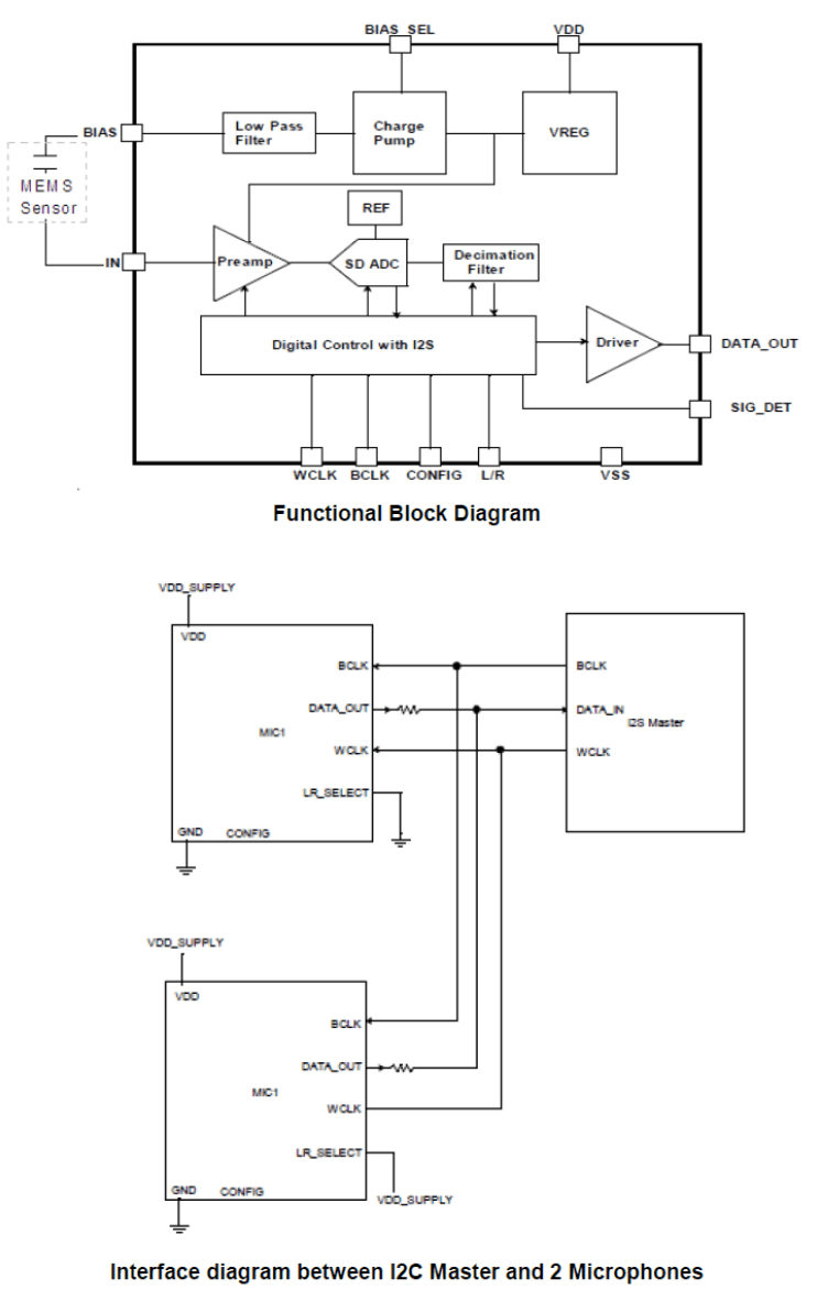
PUI Audio offers digital output MEMS microphones (designated by DMM in the PUI Audio part number) with PDM and I2S data formats. Both feature a Left/Right channel select pin for stereo audio capture and data transfer over a single data input line on a DAC or CODEC. The I2S digital MEMS (DMM-4026-B-I2S-R) microphone also offers the ability to set up microphone arrays by changing the WCLK Hold Time.
PUI Audio’s digital MEMS microphones offer a Full Power mode, a reduced sensitivity Low Power mode, and a Sleep mode for reduced current draw and battery powersavings when the microphone isn’t needed.
Modes are activated by changing the input clock frequency to the microphone.
Solder Pad and Stencil Design
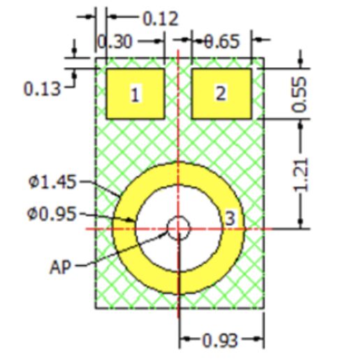
Each MEMS microphone is built for reflow soldering, where the solder joints serve as the means for electrical and mechanical connection to the PCB. On bottom-firing microphones, a solder joint also acts as the acoustic seal between the microphone sound hole and the PCB.
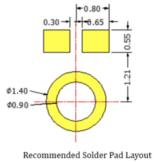
The recommended solder pad design and stencil layout is listed within the specifications for each microphone. The PCB solder pad to microphone pad ratio is 1:1
 |
 |
Solder Paste
A Type 4 no-clean solder paste is recommended to be used with PUI Audio’s MEMS microphones. The stencil thickness should be between 0.1mm to 0.12mm, with the ratio of the size of the stencil to pad being between 0.8:1 to 0.9:1 to minimize tin bead content.
For bottom-firing microphones, solder pastes with low flux content (such as Indium 8.9 HF SAC305) are recommended to prevent excessive flux from entering the microphone sound hole, causing damage.
 Pick-and-Place Operations
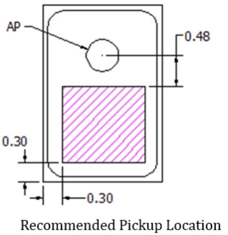
Special attention needs to be observed when programming an SMD pick-and-place machine (also known as P&Ps) to place top-firing MEMS microphones (designated with a –T within PUI Audio’s part number) due to the placement of the sound hole (referred to as the Acoustic Port or AP in the specifications) on the same surface that vacuum is applied to.
The specifications call out the recommended pickup location, and the location of the sound hole. To avoid damaging top-firing microphones, do not allow the SMD pickup nozzle to pass over the sound hole. The inside diameter of the nozzle must only move directly to the recommended pickup location, which is pink in the PUI Audio specifications.
Programming the SMD pick-and-place machine to place bottom-firing microphones is easier as the sound hole is placed on the bottom of the part.
 Reflow Soldering
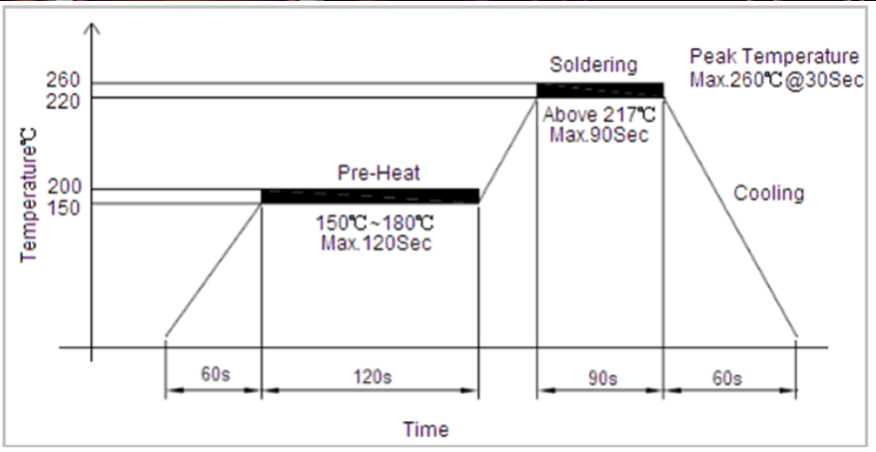
PUI Audio’s MEMS microphones feature gold-plated pads for lead-free reflow soldering. Please follow the reflow process below and do not exceed a total of three cycles. If multiple reflow cycles are required, the microphone must be allowed to return to room temperature before the start of the next reflow cycle.
Allow the microphone to rest at room temperature for a minimum of three hours before functionally testing it.
MEMS Microphone PCB Cleaning Considerations
On PCBs that contain a PUI Audio MEMS microphone, please follow these precautions to minimize potential damage to the microphone.
- Do not wash or clean PCBs after the reflow process.
- Do not expose the PCB to ultrasonic processing or cleaning.
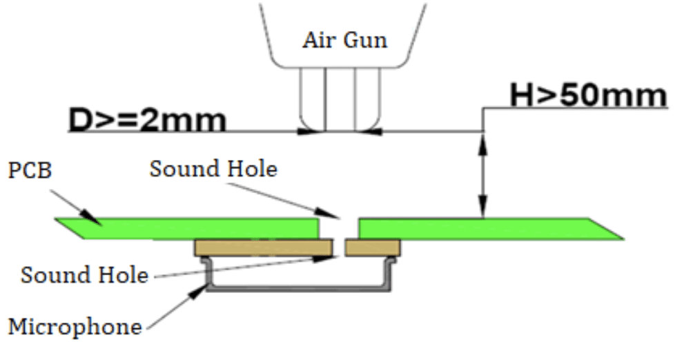
- Do not pull a vacuum over the microphone sound hole (on both top-firing and bottom-firing microphones).
- Do not apply more than 0.3mPa of air pressure into the microphone sound hole.
- If a dust removal system is used, please ensure that the air gun nozzle diameter is greater than or equal to 2mm, less than 0.3mPa of air pressure is used, the distance between the tip of the air gun nozzle and the PCB is greater than 50mm, and that the total cycle duration is less than five seconds.
- To eliminate the chance of dust entering the microphone’s sound hole, it is recommended that the sound hole be covered during the dust removal process, if possible.
Choosing the Right Microphone
Choosing the Right Microphone
Dynamic Microphone
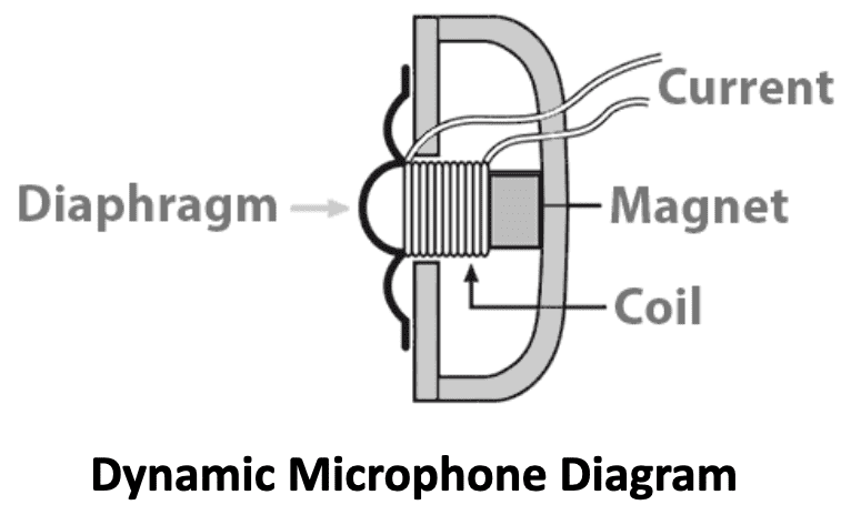 A dynamic microphone operates on the same basic electrical principles as a speaker, but in reverse. Sound waves strike the diaphragm, causing the attached voice coil to move through a magnetic gap creating current flow as the magnetic lines are broken.
Dynamic microphones are typically more resilient than other common microphones (such as condenser microphones), due to their more rugged diaphragms and are most commonly used in high SPL environments such as in concert venues for sound reinforcement applications.
While more robust than condenser microphones, dynamic microphones are often much less sensitive
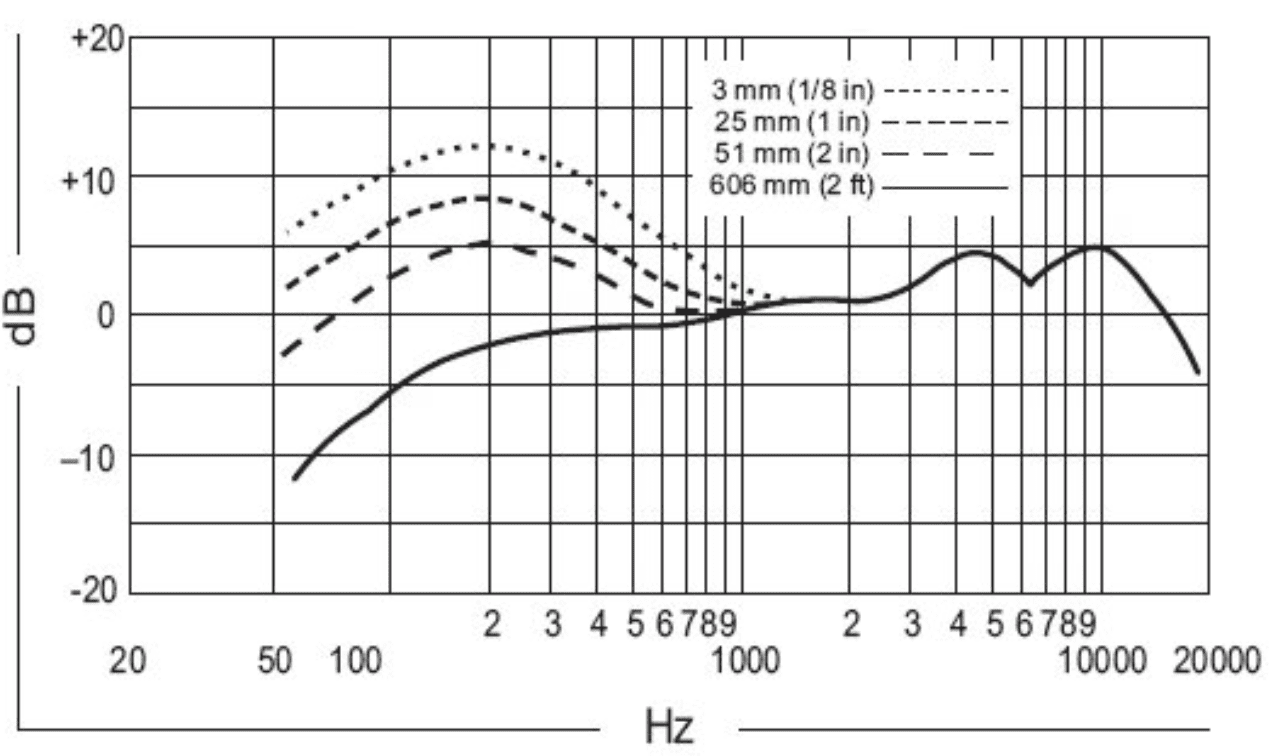
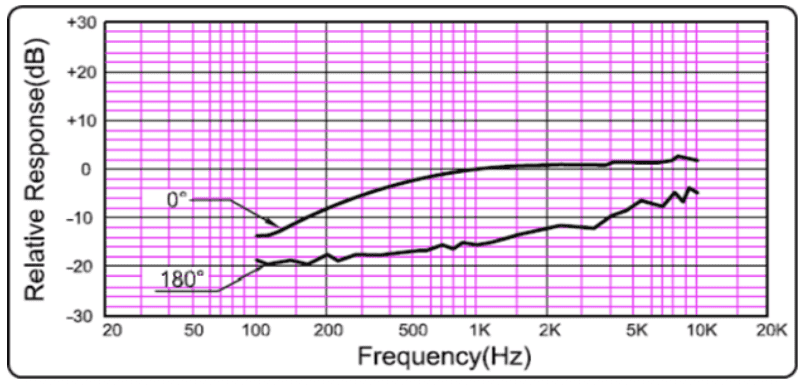
(producing less signal, or voltage with a given sound input) than condenser microphones, their low frequency performance is highly dependent on spacing from the acoustic source, and their inductance (due to the use of a high impedance coil) often reduces frequency response above 10 kHz.
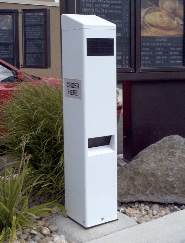
Any speaker can be used as a dynamic microphone, with many commercial drive-thru call boxes using a speaker as both the audio output and audio . Typically, the most sensitive speakers (more SPL output with a given input) will make for the most sensitive dynamic microphone and the larger the diaphragm, the narrower the polar pattern.
 |
 |
|
Sample Frequency Response of a Dynamic Microphone |
A Call Box Uses a Speaker as both a Microphone and a Speaker |
 Electret Condenser Microphone
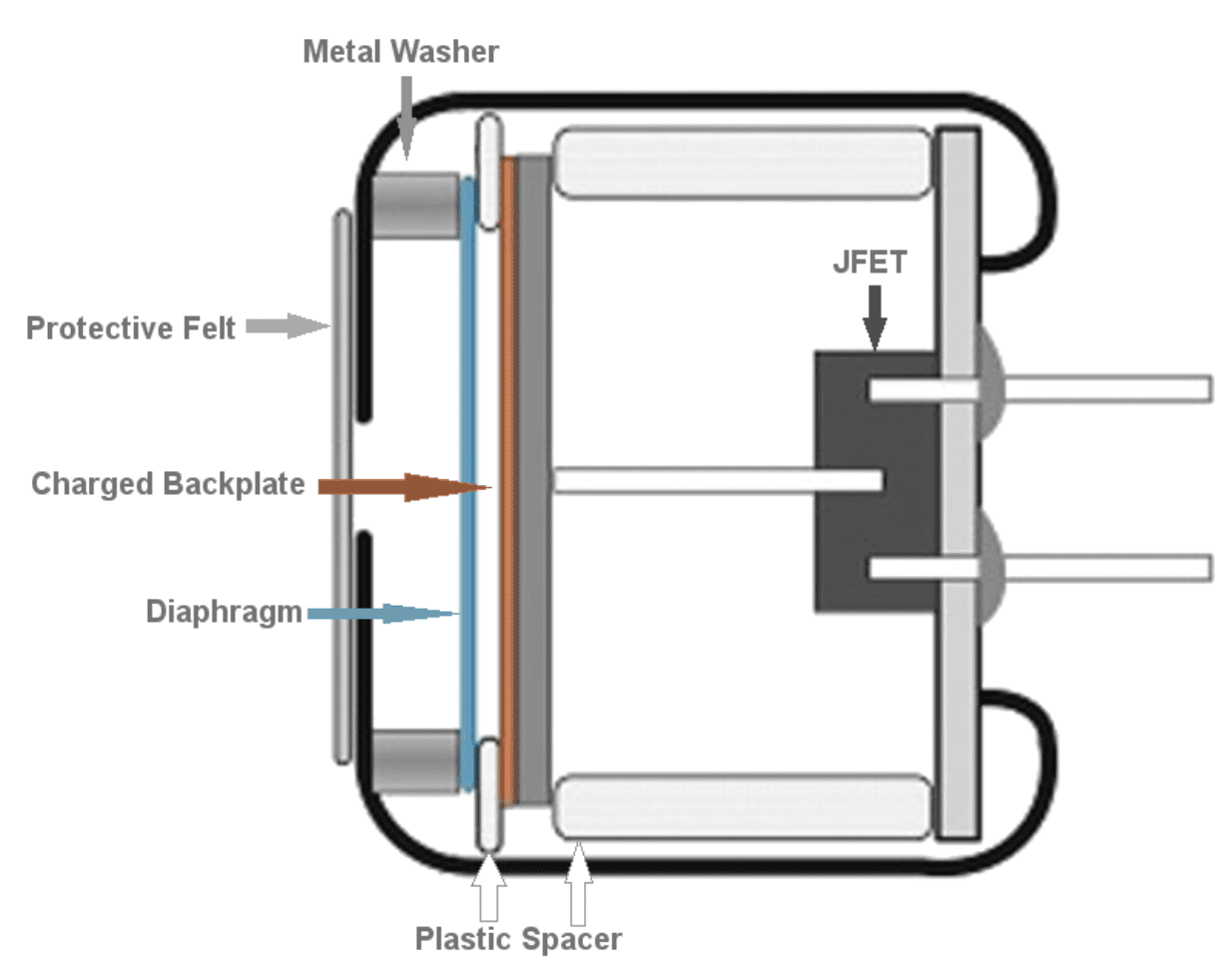
Electret condenser microphones (ECMs) operate on the principle that the diaphragm and backplate interact with each other when sound enters the microphone.
Either the diaphragm or backplate is electrically charged/polarized to create a magnetic field, the interaction within the field causes a change in capacitance, corresponding to the change in distance between the diaphragm and backplate.
A JFET within the microphone capsule acts as a pre-amplifier and changes the varying capacitance to varying voltage for use with another preamplifier or amplifier to boost the signal to a usable output.
The thin, lightweight diaphragm makes modern ECMs very sensitive when compared to dynamic microphones, with high-resolution capabilities and an ultra-wide frequency response. Most ECMs feature a housing design that is very small, making them easy to place within many different products.
Since the size of the internal diaphragm is quite small and thin, an ECM will typically have a lower Acoustic Overload Point (AOP) where the amount of input signal causes excessive distortion, when compared to a dynamic microphone.
ECMs can be made with many different types of polar patterns, to include omni-directional, uni-directional/cardioid, noise-canceling/bi-directional, and different variants of the cardioid type.
 |
 |
|
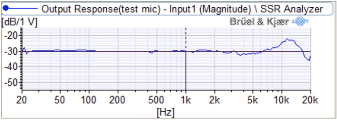
Frequency Response of the POM-2730L-HD-R ECM |
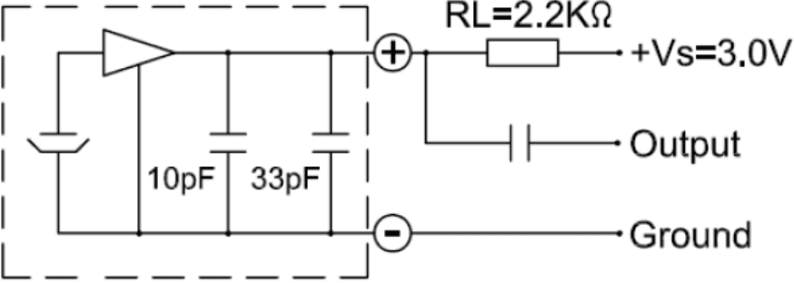
Typical ECM Drive Circuit (GSM buzz-blocking capacitors inside ECM) |
 MEMS Microphone
Most MEMS microphones work off the same principles as ECM microphones, but the working parts are scaled-down in size using Micro Electrical-Mechanical System (MEMS) processes to etch a diaphragm out of a silicon wafer, which is then combined on a PCBA with an ASIC (Application Specific Integrated Circuit).
The moveable diaphragm works in unison with a fixed and electrically charged backplate. A change in distance between these two devices, when varying air pressure (or sound) enters through the acoustic port, creates a change in capacitance. This change in capacitance is turned into a varying voltage and is then pre-amplified by the ASIC before the signal is sent on its way to the output.
MEMS microphones typically have an omni-directional polar pattern, are built with either analog or digital ASICs, and are offered in top-firing as well as down-firing configurations. Current draw is typically low—200µA or less at full voltage for an analog version, and 800µA or less at full voltage for a digital version—with most digital MEMS microphones able to be powered-down into a Low Power Mode or Sleep Mode.
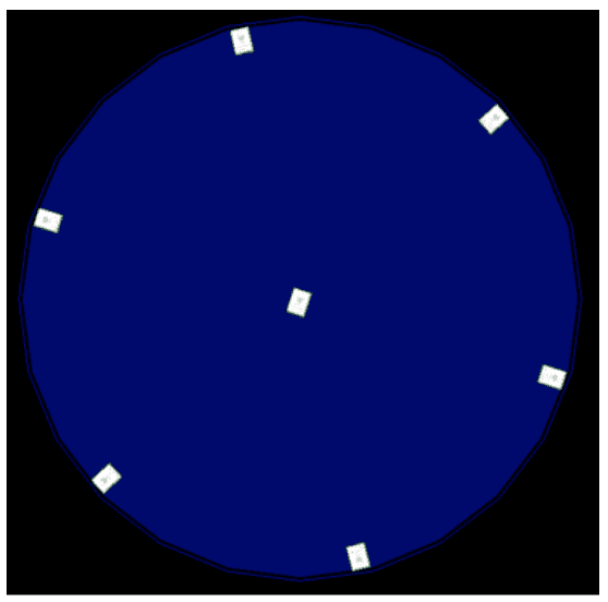
Digital MEMS microphones are sometimes used in arrays—multiple microphones splayed out in a specific pattern—for beam-forming applications. Beam-forming allows for a device to figure out which direction a sound came from due to the delay seen (from microphone to microphone) when monitoring all microphones at once, in the time domain, such as is used on the Amazon Echo™ devices.
Benefits of using a MEMS microphone include reduced power consumption, reduced size, reduced manufacturing costs with reflow soldering, as well as pick-and-place operations, and lower susceptibility to noise due to mechanical shock.
 |
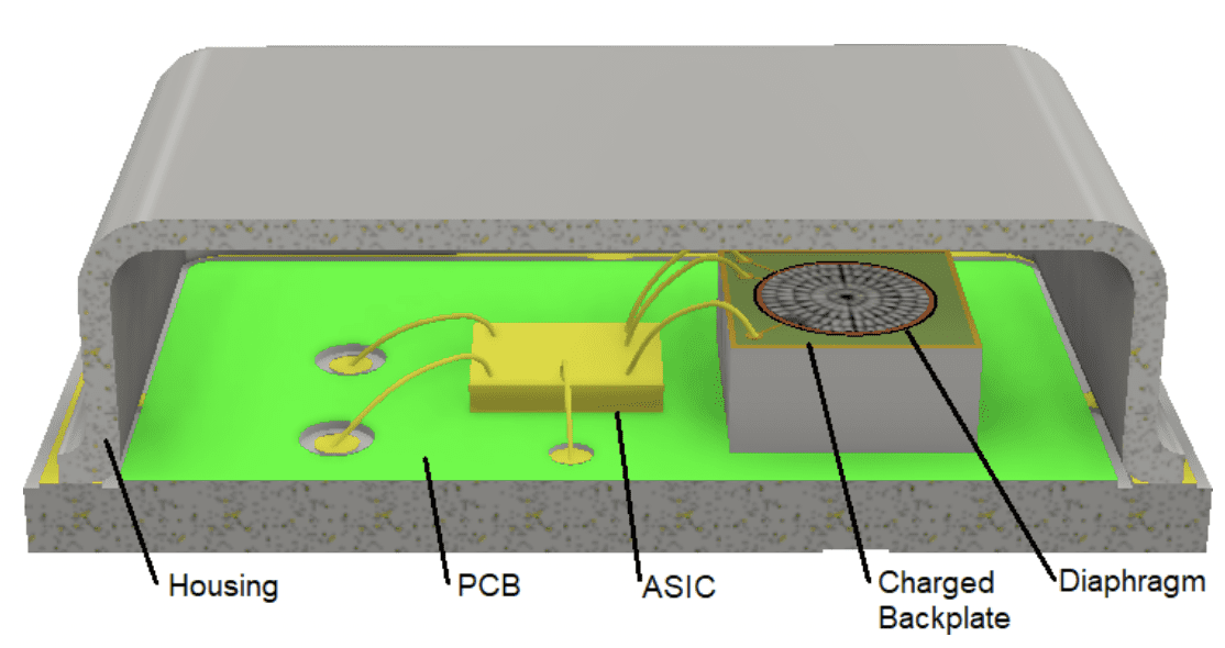 |
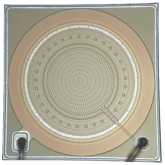
| MEMS Array | Diagram of a Down-Firing MEMS Microphone |
Microphone Sensitivity
Sensitivity is a measure of how much voltage a microphone will output, at 1 kHz, when placed at a specific distance from a 94 dB (1 pascal) acoustic source and when referencing that 0 dB is equal to 1VRMS of output, or 1VRMS/Pa.
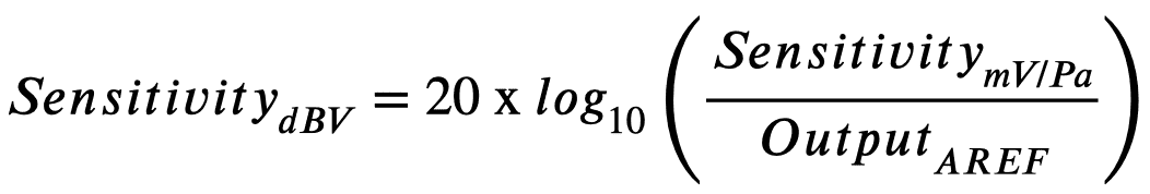
If a microphone, spaced at 50cm from a speaker generating 94 dB of output, generates roughly 500mVRMS output, it would have a sensitivity of -6 dB. Most microphones have much lower output—between 3mVRMS and 100mVRMS—and a sensitivity between -20 dB and -50 dB.
Microphone Signal-to-Noise Ratio and Dynamic Range
 Microphones have a small amount of inherent noise that is self-generated, known as the Noise Floor.
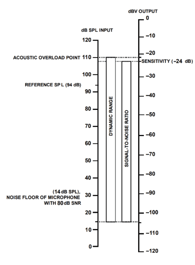
Microphones also have a maximum input SPL at which a certain amount of distortion occurs in the microphone output, known as the Acoustic Overload Point (or AOP) The difference between the rated sensitivity and the noise floor is the Signal-to-Noise ratio.
PUI Audio’s AOM-5024L-HD-R has a sensitivity of -24 dB with 3VDC input. The signal-to-noise ratio is 80 dB, making the noise level -104 dB and the noise floor 14 dB. The diagram on the right illustrates this.
To put that in perspective, if the total amount of output, for this microphone, is 63 mV/Pa, then the amount of noise in the signal is 0.0063 mV/Pa, or 0.01% of the total signal. The AOP is listed at 110 dB, making the total dynamic range 94 dB, at the rated voltage, and using the recommended bias resistor.
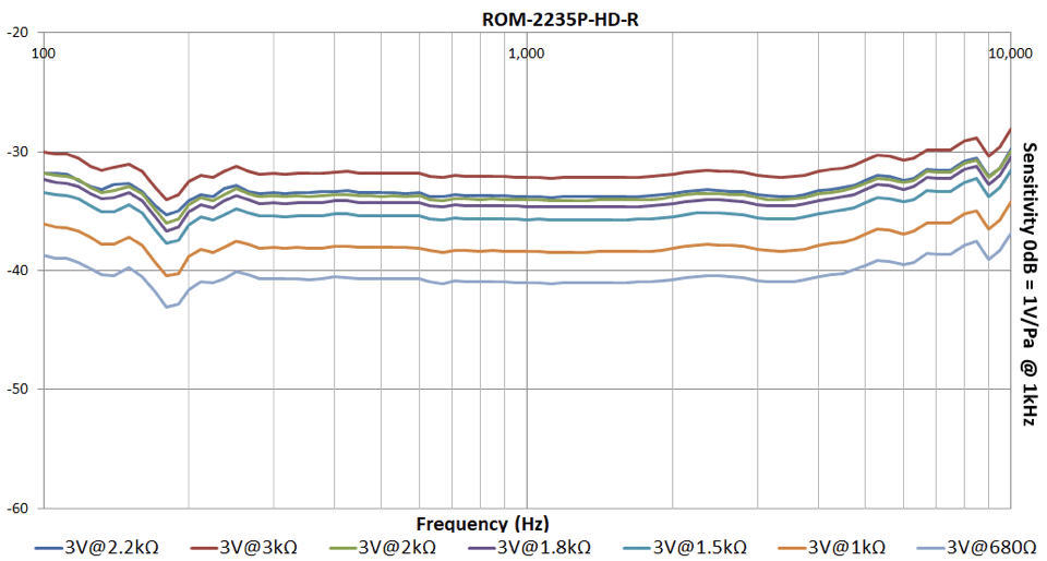
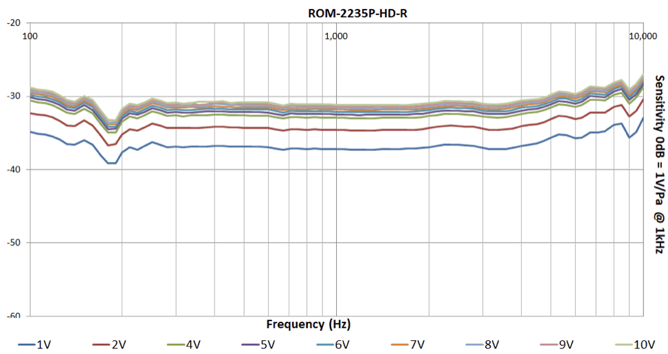
Increasing drive voltage, or selecting a bias resistor with higher resistance, increases sensitivity (as shown below) at the expense of raising the noise floor by the same amount and decreasing dynamic range.
 |
 |
Microphone Polar Patterns
Omni-Directional
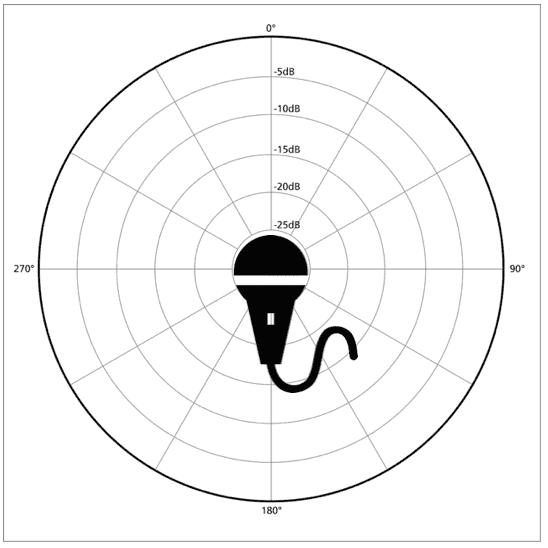 |
Omni-directional microphones capture sound equally well from all directions. Choose an omni-directional microphone if you intend to record all sounds within an environment, do not know from which direction the acoustic source will occur, or if a clean bass response is desired. Omni-directional microphones do not exhibit a proximity effect. Low frequency is captured equally well from any distance and does not dominate other frequencies.
|
Uni-Directional
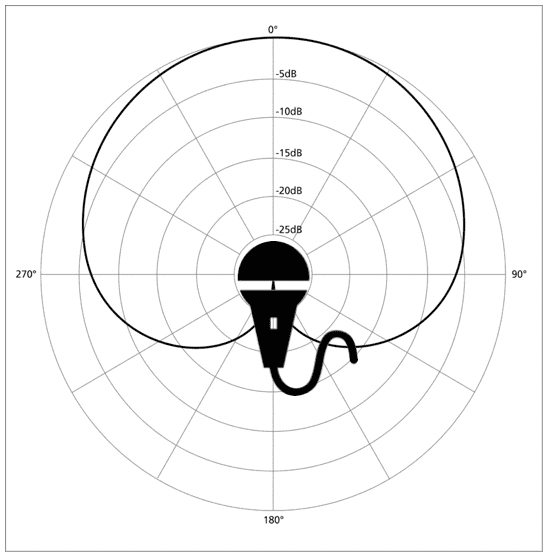 |
Inside the capsule, sound from the front takes precedence over sound captured from the rear. Sound from the rear is partially canceled-out, creating a response tailored for one direction. This microphone works well in automotive applications and in headsets. |
 Uni-directional (cardioid) microphones are built with sound holes on the front and on the rear of the capsule.
Noise Canceling
 |
This type of microphone may be used to reject lower frequencies at a distance (such as wind noise) or to capture two different audio sources at once, such as for stereo recordings. |
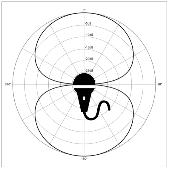
 Noise-canceling (figure-8 or bipolar) microphones feature sound holes in the front and rear of the microphone capsule that capture sound in two directions while rejecting sound to the side of the microphone.
 Making the Right Choice
With all the different types of microphones available, choosing the right one (disregarding size constraints) might seem like a daunting task. Below are things to consider before selecting a microphone.
Ambient EnvironmentConsider where the microphone is going to be used. Test ambient noise using an SPL meter or SPL phone application. Even a cheap meter, or free app, is better than not knowing the design environment. A microphone with high sensitivity isn’t always the best microphone to use. In a quiet setting, where you intend to capture an above-average sound, choose a microphone that is less sensitive to avoid capturing background noise. If your environment has both loud and quiet acoustic sources, select a microphone with the most sensitivity and highest signal-to-noise ratio. |
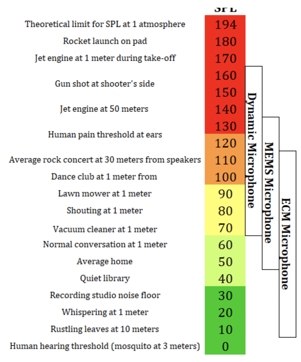 |
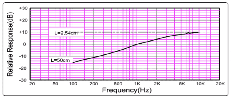
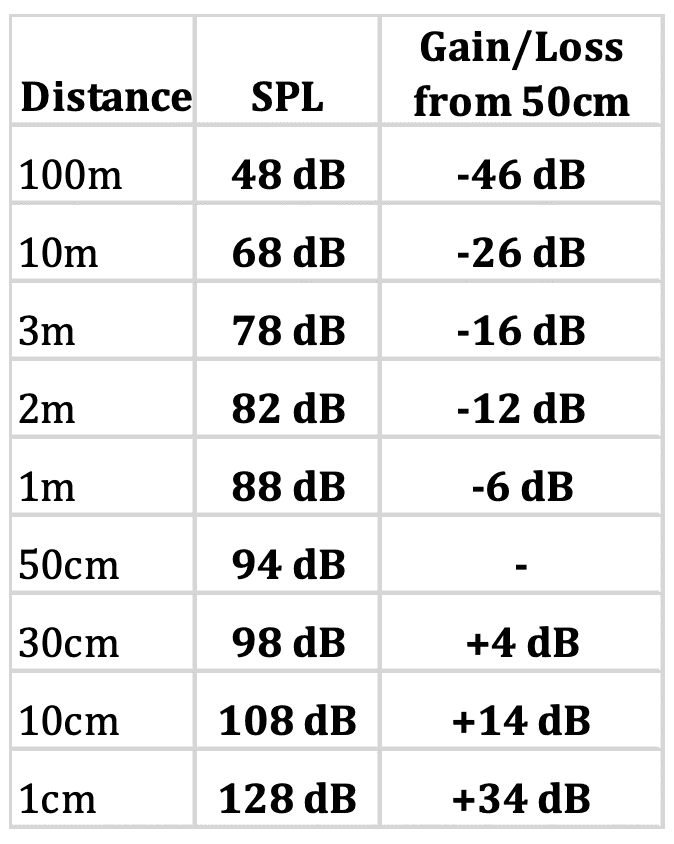
Distance Between Acoustic Source and MicrophoneSound pressure drops 6 dB for each doubling of distance between the acoustic source and the initial reference point. Most PUI Audio microphone specifications are listed with a reference distance of 50cm between a reference speaker and the microphone. Use the table to the right to convert the SPL at distance, between your acoustic source and the microphone, to ensure you are not overloading the diaphragm with sound pressure according to the microphone’s AOP. |
 |
Meet the Team – Jake
Meet the Team – Jake

Jake Cox is PUI Audio’s Inside Sales Representative for the East! Jake’s favorite part of working at PUI is helping customers find the perfect audio solution to fit their needs, every time. Not only has Jake had a big year with PUI, but he has just recently become a Dad in 2020! The best advice that Jake uses every day is to “learn something about everything, and everything about something”. Outside of work, Jake loves traveling to new places, BBQ’, riding motorcycles, and playing with his kid.
Meet The Team – Paul
Meet The Team – Paul

Paul Spain is PUI Audio’s CEO. When Paul was asked what he likes best about being on the PUI Audio team, he said, “the passion the team has for success. Everyone puts the goals of the company above their individual to-do list and offers to help their teammates when resources are taxed.” Paul works hard to keep the team motivated with a positive attitude and has a genuine interest in seeing all his employees succeed. Paul is particularly proud of how the leadership team has embraced the business operating system he introduced when he first arrived at PUI Audio in September 2019, and how disciplined the company was throughout the company is utilizing this tool to achieve transparency, accountability, and problem-solving. Outside of work Paul enjoys learning about different cultures and trying new food, reading, coaching soccer, and trying to improve his golf swing.
FLOC Dayton – First Community Support Program for PUI Audio
FLOC Dayton – First Community Support Program for PUI Audio
The team at PUI Audio has started a new Community Support program, focused on nonprofits in the Dayton region. Each quarter, we will support a new nonprofit and share communications about the organization and how we can help support their mission.
The first recipient of our Community Support Program is For Love of Children (FLOC). For Love of Children, Inc. (FLOC) is a 100% volunteer agency, with the mission to serve over 6,000 children in the greater Dayton area who are neglected, abused, in foster care or who need community resource.
Between now and June 30, we will be collecting monetary donations for FLOC as well as the items listed below. If you are interested in supporting in any way, then please contact us.
In addition, FLOC is a partner with the Dayton Mall Non-Profit Co-op. Items can be dropped off Monday-Saturday from 11am to 6pm to the right of the DSW facing SR 725 at the Dayton Mall. Spot the “LOOK FOR DONATIONS” sign.
FLOC ITEMS FOR COLLECTION:
Rice
Beans
Canned Veggies
Canned Fruit
Peanut Butter & Jelly
Pasta & Pasta sauce
Pancake Mix & Syrup
Canned ravioli and spaghetti
Canned Chili
Mac & Cheese
Snack items such as chips, crackers and cookies, raisins, fruit snacks
Pudding and Jell-O cups
Cold Cereal & Oatmeal
Canned protein such as tuna, chicken and beef
Juice, canned milk, bottled water
Baby items (formula, diapers, wipes)
School Supplies
Personal items (shampoo, tooth brushes and toothpaste, soap, deodorant)
Paper supplies (toilet paper, paper plates, and paper towels)
Books & games
Meet the Team – Betty Quinn
Meet the Team – Betty Quinn
Betty Quinn is the Sales Manager at PUI Audio. Betty loves her job because everyone shares the same vision and is dedicated to making sure that as a team, we take care of our customers by offering the best customer service, quality products and innovative solutions. As far as the achievements that she is most proud of, Betty has shared that it is her longevity with the company. This has given her the opportunity to work with all Departments and learn the business from all directions. She has made lifelong friendships along the way.
The best advice that Betty has learned is to Work Smarter, Not Harder.
When she is not working, Betty enjoys spending time with her family, especially now that she is a new Grandma.
Community Spotlight: Dayton Kroc Center SC and A Winning Season
Community Spotlight: Dayton Kroc Center SC and A Winning Season
The mission of the Dayton Kroc Center SC has been shared with the PUI Audio team through our CEO, Paul Spain. The cornerstone of Dayton Kroc Center SC is a sponsor-subsidized fee structure to enable any child the opportunity to play club level soccer, which is often cost prohibitive for many families. This allows children from all income levels to experience their full potential through focused coaching, training, mentoring and competitive club soccer games. The geographical focus for the program is Dayton’s urban core.
After relocating to Dayton in September 2019, Paul, a soccer player and coach, made connections in the local soccer community, including the Dayton Kroc Center SC. After being a back-up coach in 2020, Paul took on the role of head coach for the newly formed U12 boys’ team in the spring of 2021.
The first season was very successful with the team winning their division in the Miami Valley Youth Soccer Association. This truly was a great accomplishment for the entire team, and the team at PUI Audio looks forward to supporting the Dayton Kroc Center SC in the future.
PUI Audio Simulator Receives Copyright
PUI Audio Simulator Receives Copyright
FOR IMMEDIATE RELEASE
6/16/21
PUI Audio Simulator receives copyright
Dayton, Oh — The PUI Audio Simulator has received an official copyright notice from the U.S. Department of Copyright, giving PUI customers and distributors exclusive access to one-of-a-kind technology that cannot be duplicated.
The copyright award is an acknowledgement of the uniqueness of the simulator tool, as well as its unmatched and innovative place in the market.
“When we set out to give our customers access to a tool that made their jobs easier and removed barriers to having their products heard, we wanted to do something that had never been done before,” said PUI CEO Paul Spain. “The copyright award from the U.S. Copyright Office is an acknowledgement that we met that goal, and it inspires us to keep delivering new and exciting ways for our customers to continue to be heard in the marketplace.”
The PUI Audio Simulator was officially unveiled company-wide to the PUI sales team and manufacturing representative sales network on February 18 during the national sales kickoff, which took place virtually this year.
The simulation tool is the first in the industry and is a web-based application with the ability to digitally replicate actual frequencies and varying types of sound waves. The tool allows users to log in, explore, select and test audio components before identifying what parts and components they need to implement the exact solution they need.
Users of the simulator are able to experiment with sound variations to identify the exact output they need. Users can then identify the components necessary to achieve the desired goals and reach out to the sales team for quotes and solutions. Users unsure of what types of components they might need, can take the tool a step further and utilize the product wizard, answering a few simple questions to identify the right mix.
PUI first designed the tool to replicate the benefits of an in-person meeting with a PUI representative during the COVID-19 pandemic. As the company embarked on the project, Spain said the team realized the benefits of the project would have far reaching benefits beyond the temporary need for a virtual solution.
Spain said PUI is currently developing additional ways to enhance the tool, and plans to roll out continuous upgrades to the application throughout the coming years.
“Our goal will forever be to provide our customers access to expertise that empower them to be heard,” he said. “We are making a concentrated investment to continue to innovate ways to enhance audio components with expertise and give our customers the peace of mind they need to get their products right, the first time.” The simulator is currently available to PUI’s existing customer base, as well as through the company’s website and other channels, so that anyone can use it, following registration on the application.
PUI Audio, Inc. is a Dayton-based audio component manufacturer. Founded in 1972, the company has built a strong reputation for its creative solutions and engineering expertise, helping clients in medical, industrial, security and consumer markets to, “Be heard!” no matter what the need.
For media inquiries, please contact:
Erin Ruef
Vice President of Marketing
ruef@puiaudio.com
937-475-4799
High Temperature Parts
High Temperature Parts
PUI Audio offers a wide array of high-temperature parts including Speakers, Indicators, and Transducers. We offer over 20 different parts designed for use in extreme temperature environments. Many of these parts work in temperatures up to 105°C/221°F and as low as -40°C/-40°F.
High Temperature Parts- Speakers.pdf
Talk to one of our technical sales reps today to learn more
Press Release
Press Release
PUI Expands Catalogue with New Product Launches
The team at PUI Audio has been hard at work during 2021 developing new products, making it
easier than ever for customers to be heard.
From a new family of evaluation boards to IP rated waterproof MEMS microphones, the
The product development team has been able to launch several exciting new products so far in
2021.
“Innovation is key to providing our customers the solutions they need,” said PUI CEO Paul
Spain, “Our product catalogue is continually evolving because our products are enhanced with
engineering expertise, meaning we hear what our customers need and get to work creating
products that solve their problems proactively.”
The new lineup includes several products designed to enhance the durability and performance
of end products, meaning PUI customers can be heard better and louder than ever before.
A new line of evaluation boards has been added to the catalogue, including five models for
various applications. These boards feature some of our smallest electromechanical
transducers and afford customers the ability to quickly and easily test the products without
the need to spin PCB’s just for evaluation.
· Evaluation Board: SMT-0540-T-8-EB-R
· Evaluation Board: SMT-0540-S-2-EB-R
· Evaluation Board: SMT-0440-T-2-EB-R
· Evaluation Board SMT-0440-S-EB-R
· Evaluation Board SMT-0340-T-EB-R
The team has also introduced several new parts that include features to enhance durability
and protect components from weather and environmental threats. New MEMS microphones
that include waterproof mesh pre-applied making them IP57 rated, as well as a new
powerful enclosed speaker capable of producing extremely loud output while offering plug-and-play operation with smart amplifiers, and additional parts with high-temperature ratings
designed for use in extreme temperature environments.
· Waterproof MEMS Microphones: AMM-2742-T-WP-R
· Waterproof MEMS Microphones: AMM-3742-T-WP-R
· Waterproof MEMS Microphones: DMM-4326-T-WP-R
· Enclosed Speaker: ASE02008MS-LW100-R
· High-temperature parts
Full spec sheets and product information for all the new products, as well as existing
products in the lineup, are available on the PUI Audio website at PUIAudio.com–
PUI Audio, Inc. is a Dayton-based audio component manufacturer. Founded in 1972, the
company has built a strong reputation for its creative solutions and engineering
expertise, helping clients in medical, industrial, security and consumer markets to, “Be
heard!” no matter what the need.