Meet with an engineer
Latest News
Select a Category
Select A Product Type
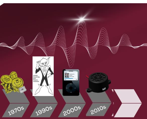
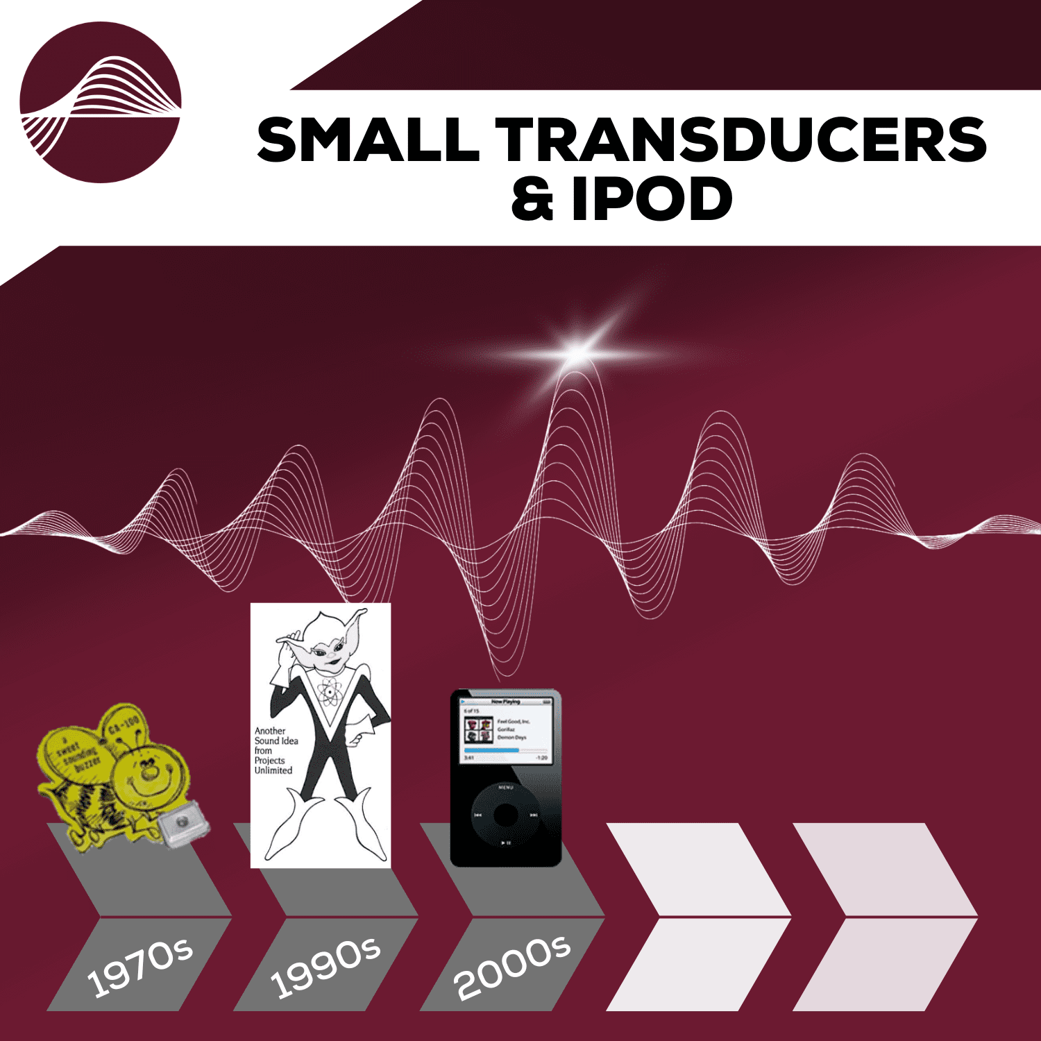
Innovation Over Fifty Years: Focus on 2000s
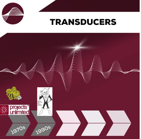
Innovation Over 50 Years: Focus on 1980s/1990s

Innovation Over 50 Years: Focus on the 1970s
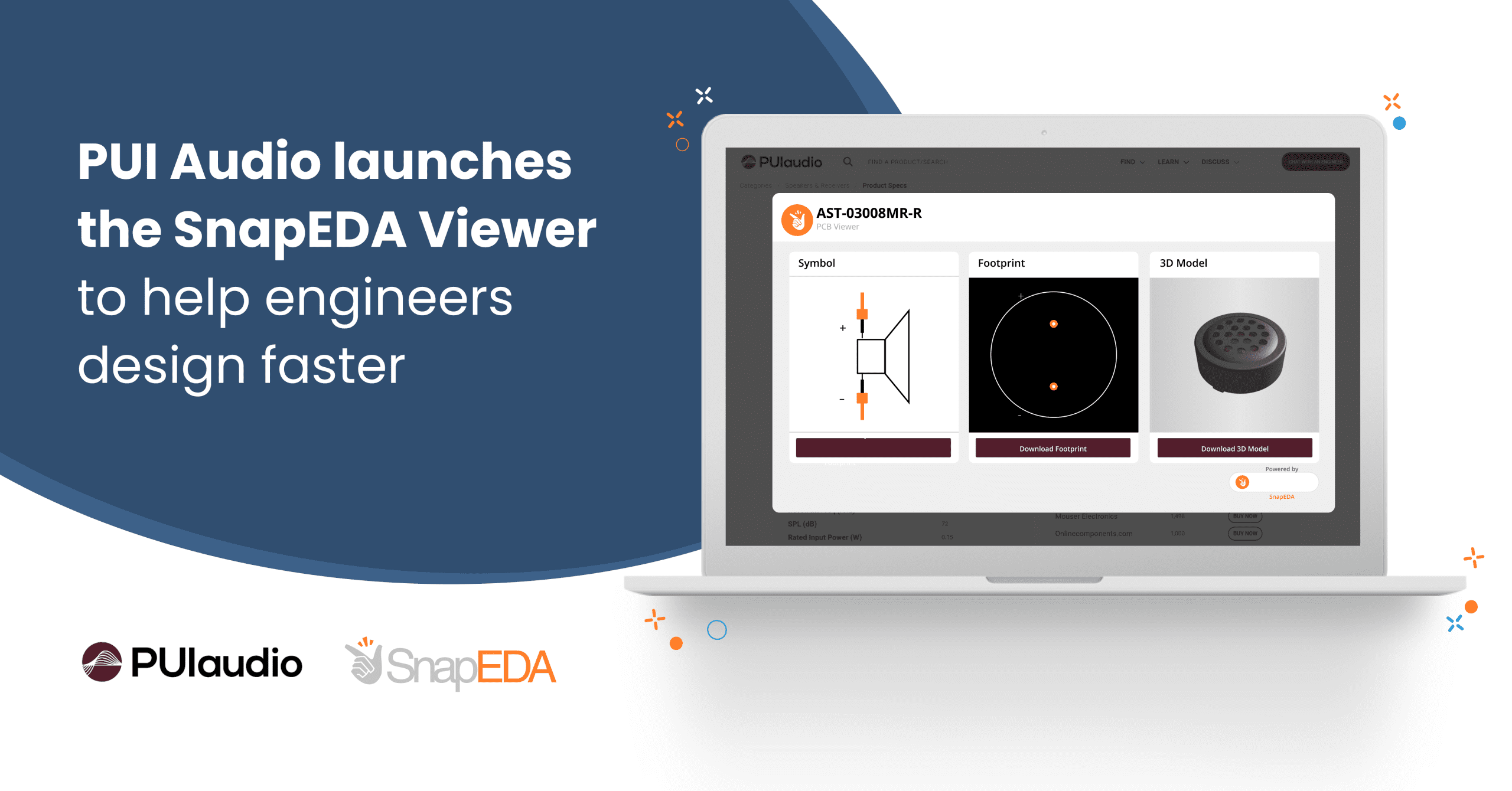
PUI Audio makes it easier to design electronics faster with new SnapEDA experience

Welcome to PUI Audio’s New Website

Overcoming the Pitfalls of Poor Audio

How to Choose the Right IEC 60601-1-8 Speaker

Custom Audio Solutions for Your Unique Applications

Wide-Band MEMS Microphones Application Guide

Choosing the Right Microphone